Normalized Er Diagram For Student Database
Examples
Entity Relationship Diagram Examples
Know it All about ER Diagrams
Do you have a vast database system? Are you having difficulty making the necessary connections between different entities? Well, then ER diagrams are here to help!
What is an ER Diagram?
An ER diagram or Entity Relationship Diagram (ERD) is a type of flowchart or graphical approach that helps you illustrate how different entities relate to each other. It is a standard way of modeling databases and business processes.
Now that you have a general understanding of what ER diagrams are, we will list a few instances where you can draw them. As mentioned above, ER diagrams (or ER Models) are used in database designs and business processes. Some of them are as follows:
- Database Design: Sometimes while altering the structure of a database, it can be risky to make such massive changes. So, ERDs are the best tool to visualize the ideas, which helps identify the mistakes and correct them before executing the changes.
- Software Engineering: For an information systems project, ERDs are the first step to determine what is required. It is also used to model a database.
- Troubleshooting Databases: ER diagrams help you have a complete picture of the database, which helps you easily observe the entities, their attributes, and relationships with others. This then allows you to analyze the existing database and recognize the problems quickly.
- BPR (Business Process Re-engineering): During Business Process Re-engineering, ER diagrams help you analyze the databases and then model a better database setup.
- Research: A lot of the research is based on interlinkages and observing relationships between different entities. Thus ER diagrams come in handy in such scenarios as well.
EdrawMax
All-in-One Diagram Software
Create more than 280 types of diagrams effortlessly
Start diagramming with various templates and symbols easily
- Superior file compatibility: Import and export drawings to various file formats, such as Visio
- Cross-platform supported (Windows, Mac, Linux, Web)
ER Diagrams Examples of Common Scenarios
We mentioned a few scenarios where ER diagrams are used. Now, let's look at a few real-life examples of ER diagrams.
1. ER Diagram of Hotel Management System
The ER diagram given below is for a hotel management system. The diagram shows all the entities and the relationships between them. The data is structured and shows all the instruments of database tables.
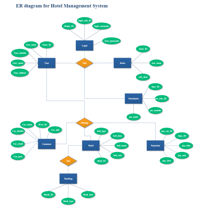
Entities and their Attributes
The main entities of the Hotel Management System are a hotel, rooms, services, payments, bookings, and customers.
- Hotel Entity: Attributes are hotel_type, hotel_name, hotel_rent, hotel_ID and hotel_description.
- Payments Entity: Attributes are payment customer ID, payment_ID, payment_description, payment_date, payment_amount.
- Customer Entity: Attributes are customer_pass, customer_email, customer_mobile, customer_ID, customer_name, customer_address.
- Booking Entity: Attributes are booking_description, booking_type, booking_ID.
All the entities are normalized, and the duplicity of records is reduced. Furthermore, there are one-to-one and one-to-many relationships.
2. ER Diagram of Database - University Database
A university database consists of all the information regarding a student. Although such a database is not suitable for a large institution, it illustrates relationships that help resolve queries.
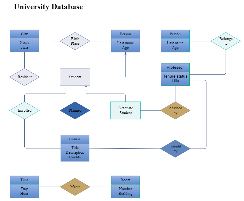
Entities and Attributes
- Student Entity: Attributes are a name, age, birthplace, birthday, etc.
- Course Entity: Attributes are course title, course description, credit hours, course teacher.
- Professor Entity: Attributes are tenure status, job title, name, age.
A student enrolls in many courses, so it's a one-to-many relationship.
3. ER Diagram of Library Management System
The library management system has a database that shows the relationships between the entities such as a book, publisher, and member. Since this is a simple system, it has only three entities. Other systems can be more complex with a more significant number of entities such as staff etc.
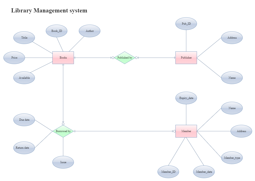
Entities and Attributes
- Book Entity: It has author, book_ID, title, price, and availability.
- Publisher Entity: It has publisher_ID, publisher_address, and publisher_name.
- Member Entity: It has member_ID, member_date, member_type, member_address, member_name, and expiry_date.
In this example, we can again see one-to-one and one-to-many relationships. A member can borrow many books, but only one reader can borrow one book. So, the relationship is 1: Many.
4. ER Diagram of Online Shopping System
The ER diagram given below is for an Online Shopping Management System. The purpose of this ER diagram is to use a database and Java to create a good project.
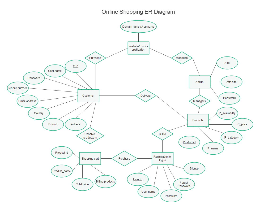
Entities and Attributes
- Website/Application Entity: Attributes are domain name and app name.
- Customer Entity: Attributes are username, password, email address, mobile number, country name, district, address, C_id.
- Products Entity: Attributes are product ID, P_name, P_category, P_price, P_availability.
- Admin Entity: Attributes are username, password, A_id.
- Shopping Cart Entity: Attributes are product id, product name, total price, billing products.
- Registration Entity: Attributes are user id, username, password, forgot password, signup.
We can observe some relationships between the entity and its attributes, such as the entity mobile app and its domain name attribute. This shows that the project head will create the project based on software. Besides, we can also find other relationships between customers and admin, products and admin, etc.
5. ER Diagram of NoSQL Database
Given below is a template for a NoSQL database ER diagram.
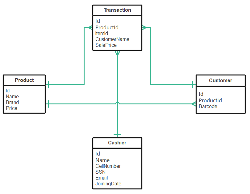
Entities and Attributes
- Transaction Entity: Attributes are transaction Id, productId, Item Id, customer name, and sale price.
- Customer Entity: Attributes are customer id, product id, and barcode.
- Products Entity: Attributes are product id, product name, product brand, product price.
- Cashier Entity: Attributes are cashier id, cashier name, cashier cell number, cashier social security number, cashier email, and cashier's joining date.
You can observe the relationships between the product and customer and product and transaction. This is a one-to-many relationship. Other relationships include cashier to transaction and transaction to the customer.
6. ER Diagram of One-to-Many Relationship
Following is an example of an ER diagram that is showing a one-to-many relationship.
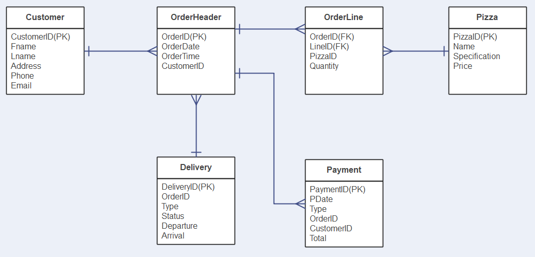
Entities and Attributes
- Delivery Entity: Attributes are delivery ID, order ID, type, status, departure, arrival.
- Customer Entity: Attributes are customer ID, phone, email, customer's address.
- Payment Entity: Attributes are payment id, payment date, type, order ID, customer ID, total payment.
- Order Header Entity: Attributes are order ID, order date, order time, and customer ID.
- Order Line Entity: Attributes are order id, line id, pizza id, and quantity.
- Pizza Entity: Attributes are pizza id, name, specification, and price.
You can observe the one-to-many relationships such as order time of order header entity is linked to the payment type, payment date, and order id of the payment entity.
7. ER Diagram of Banking System
The ER diagram given below is for the Bank Management System. It illustrates critical information about the bank.
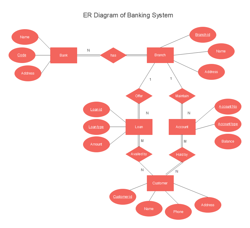
Entities and Attributes
- Bank Entity: Attributes are bank name, code, and address.
- Customer Entity: Attributes are customer_id, name, phone number, and customer's address.
- Branch Entity: Attributes are branch_id, branch name, and branch address.
- Account Entity: Attributes are account_number, account_type, and account balance.
- Loan Entity: Attributes are loan_id, loan_type, and loan amount.
You can observe different relationships, such as a branch offering many loans, so 1: N relationship. Other relationships such as M: N can also be observed.
8. ER Diagram of Hospital Management System
The below ER diagram is for a hospital management system. You can see the different entities and how they relate to each other.
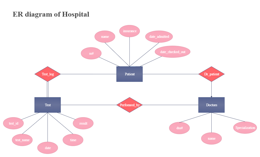
Entities and Attributes
- Patient Entity: Attributes are social security number, name, insurance, date of admission, date of checking out.
- Doctors Entity: Attributes are dss#, name, specialization.
- Test Entity: Attributes are test_id, test_name, test date, test time, test result.
You can observe that a doctor treats many patients, and a patient might go to different doctors. It is an M: N relationship. Other relationships can also be observed.
Use EdrawMax for ER Diagram Creation
Drawing an ER diagram is a tiresome and lengthy process. So, we suggest that you use EdrawMax to ease your difficulty. EdrawMax is an excellent ER diagram software for drawing and mapping that makes the process shorter and quicker. You can use a wide variety of entity relationship diagram examples available for free.
As the best alternative to Visio, EdrawMax supports drawing entity relationship diagram, Chen ERD, Martin ERD, Express-G, ORM diagram, database model diagram, etc. By using easy-to-use drawing tools, together with many pre-drawn ER diagram templates and more than 6000 symbols and icons, creating ER diagrams can be amazingly fast and easy.
Related Articles
Source: https://www.edrawsoft.com/er-diagram-examples.html
Posted by: dereknielsene0192661.blogspot.com
Manual For Wood Frame Construction
 Тема: Строительство каркасного дома. Книги (Прочитано 66962 раз)
0 Пользователей и 1 Гость просматривают эту тему.
- Мастеровой »
- Книги, журналы, видео, сайты. »
- Книги, журналы, видео - Общие темы »
- Плотницкое дело (Модераторы: BOBz, minjka) »
- Строительство каркасного дома. Книги
Source: https://woodcraftsman.ru/index.php?topic=1335.0
Posted by: dereknielsene0192661.blogspot.com
Bmw E90 Rear Shock Diagram
Can't find your vehicle? Click here.
![]()
- Project Time: 3 hours
- Tab: $300
- Talent
- Tools: Flathead & Phillips screwdrivers, 16mm, 17mm, 8mm sockets. 16mm, 17mm wrenches.
- Parts Required: Rear shock, rear shock thrust bearing and mounts
- Performance Gain: Repair faulty rear shock and mounts
- Complementary Modification: Inspect coil springs
When replacing your rear shocks, always replace them in a pair.
I suggest replacing the lower shock mounts also. The shock mounts tend to wear and fall apart over time. It's better to replace them while you are servicing the shocks than to have to go back to them later. Always replace your shocks in pairs and any associated parts that look worn. You'll want to raise your vehicle high enough to fit a jack under the rear swing arm. This helps when installing new shock into trunk shock tower.
In this tech article, I will go over how to replace the rear shocks on BMW E90 vehicles.
Raise rear of vehicle and support safely on jack stands. See our tech article on jacking up your vehicle. When jacking, get vehicle as high as possible. You will have to be able to fit a hydraulic jack under the rear trailing arm.
Check out our complete Technical Article Directory for guides to many other procedures.
Check out our Basic Maintenance section, which has all the parts you'll need to get your vehicle running its best, including filters, fluids, brakes, spark plugs, lighting, and more for your E90!
Hot tip
Replace one side at a time
Project Photos


Got more questions? Ask any of our automotive experts.
Source: https://www.pelicanparts.com/BMW/techarticles/BMW-3-Series-E90/SUSPEN-Rear_Shock_Replacement/SUSPEN-Rear_Shock_Replacement.htm
Posted by: dereknielsene0192661.blogspot.com

